The structural analysis software RFEM 6 is the basis of a modular software system. The main program RFEM 6 is used to define structures, materials, and loads of planar and spatial structural systems consisting of plates, walls, shells, and members. The program also allows you to create combined structures as well as to model solid and contact elements.
RSTAB 9 is a powerful analysis and design software for 3D beam, frame, or truss structure calculations, reflecting the current state of the art and helping structural engineers meet requirements in modern civil engineering.
Do you often spend too long calculating cross-sections? Dlubal Software and the RSECTION stand-alone program facilitate your work by determining section properties of various cross-sections and performing a subsequent stress analysis.
Do you always know where the wind is blowing from? From the direction of innovation, of course! With RWIND 2, you have a program at your side that uses a digital wind tunnel for the numerical simulation of wind flows. The program simulates these flows around any building geometry and determines the wind loads on the surfaces.
Are you looking for an overview of snow load zones, wind zones, and seismic zones? Then you are in the right place. Use the Geo-Zone Tool to determine quickly and efficiently snow loads, wind speeds, and seismic data according to ASCE 7‑16 and other international standards.
Would you like to try out the capabilities of the Dlubal Software programs? You have the opportunity to do so! The free 90-day full version allows you to thoroughly test all our programs.
If several solids adjoin each other, they are usually rigidly connected to each other. By means of surface releases and what are known as contact solids, the contact conditions of the solids can be easily adapted to the respective conditions.
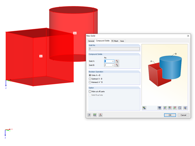
For models consisting of solids, you can also create a compound solid. Using Boolean operations, you can unite, subtract, or intersect two solids.
There is an option to convert an intersection to a line. This option allows you to create the intersection manually. Here is an example:
1. First, an intersection between two objects is created, here using the "New Compound Solid" command:
In this specific case, the cylinder is subtracted from the cuboid, thus creating an intersection:
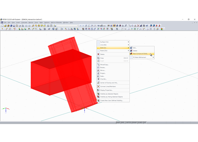
2. This intersection is now "converted into lines". For this, select all involved objects and in the shortcut menu, select "Convert into Line" under "Intersection":
3. The new lines are used to create new surfaces or modify existing ones. You can change the boundary lines of a surface by selecting them again. In particular, the intersection area must be modeled as a quadrangle surface:
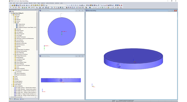
4. Finally, it is necessary to create the solid again:
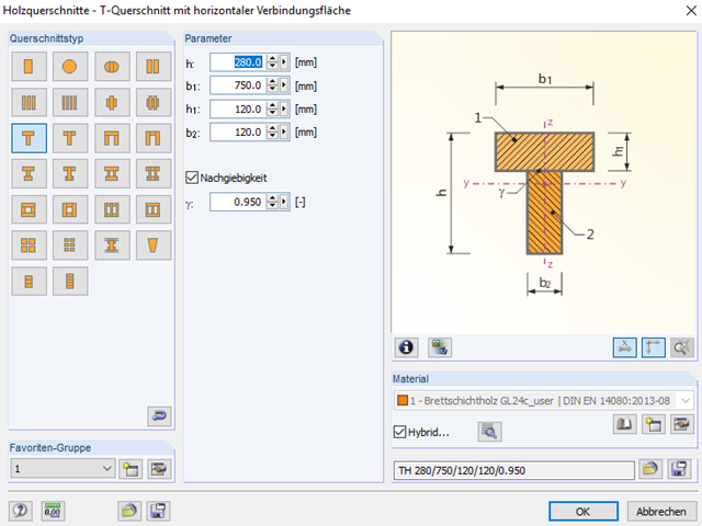
The "gamma factor" can be determined according to EN 1995‑1‑1, Annex B. It depends, among other things, on the slip modulus of the fastener and their spacings, as well as the span.
However, this method has limitations. Therefore, you can also create a pure member model and read off or design the internal forces directly. This option is described in more detail in the Technical Article.